
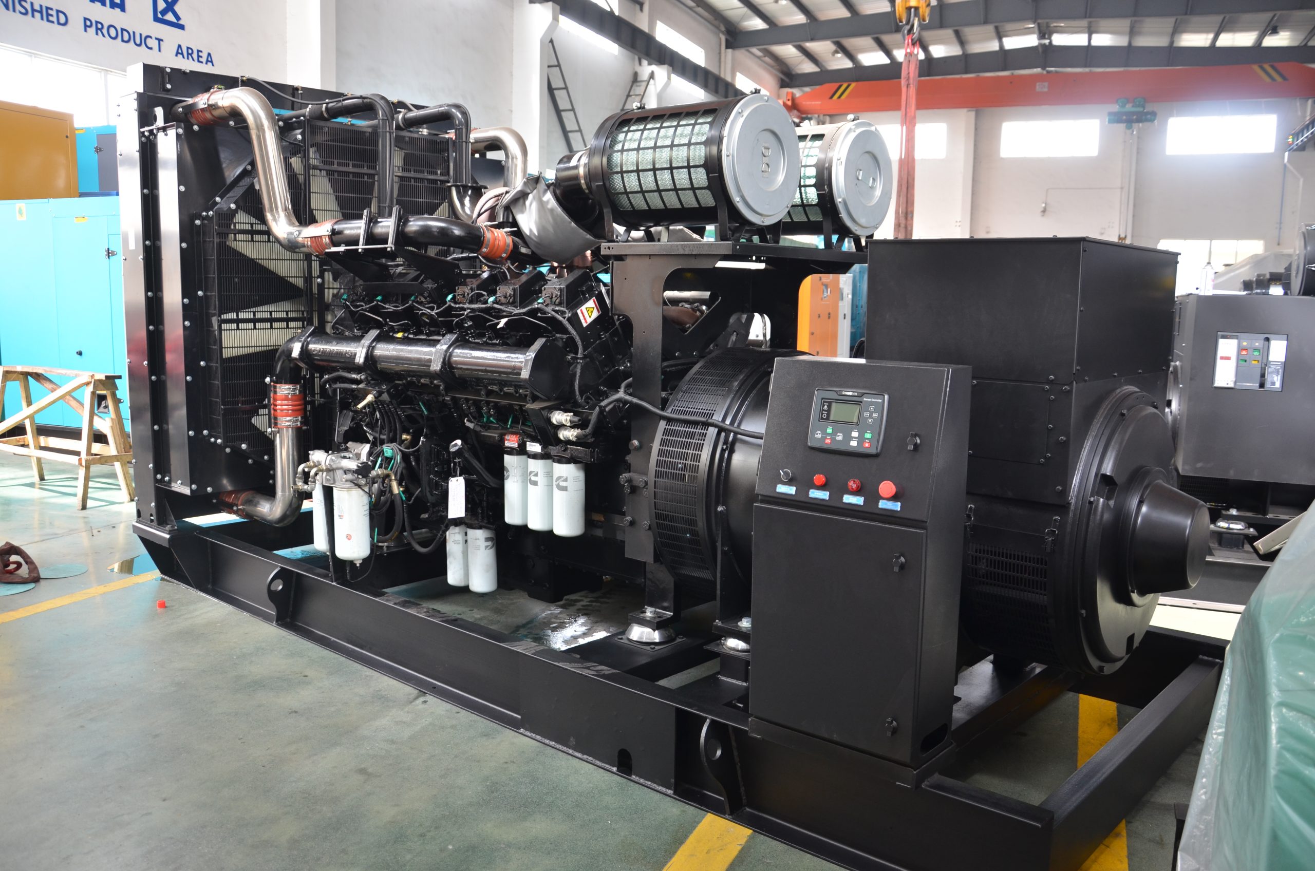
CCEC KTA50-G8 Generator Engines
| Engine Model | KTA50-G8 |
| Standby Power | 1915 HP (1429 kW) @ 1500 RPM |
| Prime Power | 1608 HP (1200 kW) @ 1500 RPM |
| Compression Ratio | 13.9 : 1 |
| Type | 4 Cycle; 12 Cylinder |
| Fuel System | PT-STC |
| Aspiration | Turbocharged & Aftercooled |
| Emission Standard | Euro II |
| Displacement | 50 L |
| Bore * Stroke | 159 mm * 159 mm |
| Packing Size (L * W * H) | 2794 mm * 1507 mm * 1846 mm |
General Infomation of CCEC KTA50-G8 Generator Engines
| General Infomation of CCEC KTA50-G8 Generator Engine | |||
| Engine Model | KTA50-G8 | Configuration | D283022DX02 |
| Performance Curve | FR – 6243 (1P / 2L) / FR – 6351 (2P / 2L) | CPL No. | 2354 (1P / 2L) / 2859 (2P / 2L) |
| Type | 4 – Cycle; 60° Vee; 16 – Cylinder Diesel | Aspiration | Turbocharged & Low Temp. Aftercooled |
| Compression Ratio | 14.9 : 1 | Displacement | 3067 in3 / 50.3 L |
| Overload Power | 1915 HP (1429 kW) @ 1500 RPM | Prime Power | 1608 HP (1200 kW) @ 1500 RPM |
| Installation Data of CCEC KTA50-G8 Generator Engine | |||
| Bore * Stroke | 159 mm * 159 mm / 6.25 in * 6.25 in | Dry Weight – Fan to Flywheel Engine | 11820 lb / 5360 kg |
| Wet Weight – Fan to Flywheel Engine | 12485 lb / 5662 kg | Dry Weight – Heat Exchanger Cooled Engine | N / A |
| Wet Weight – Heat Exchanger Cooled Engine | N / A | Maximum Bending Moment at Rear Face of Block | 4500 lb.ft / 6100 N.m |
| Moment of Inertia of Rotating Components – with FW 6009 Flywheel | 301 lbm.ft2 / 12.7 kg.m2 | Moment of Inertia of Rotating Components – with FW 6017 Flywheel | 515 lbm.ft2 / 21.7 kg.m2 |
| Center of Gravity from Rear Face of Flywheel Housing (FH 6024) | 47.5 in / 1206 mm | Center of Gravity Above Crankshaft Centerline | 11.0 in / 279 mm |
| Maximum Static Loading at Rear Main Bearing | 2000 lb / 908 kg | Steady State Stability Band at any Constant Load | + / – 0.25 % |
| Minimum Ambient Temperature for Aided (with Coolant Heater) Cold Start within 10 seconds | 50 °F / 10 °C | Minimum Ambient Temperature for Unaided Cold Start | 45 °F / 7 °C |
| Excludes Exhaust Noise; at Rated Load and 7.5 m (24.6 ft); 1500 RPM | 92.4 dBa | Exhaust Noise at 1 m Horizontally from Centerline of Exhaust Pipe Outlet Upwards at 45° | N / A |
Engine Performance Data CCEC KTA50-G8 Generator Engines
| Performance Data of CCEC KTA50-G8 Generator Engine | |||||
| Stanby Power | Prime Power | Stanby Power | Prime Power | ||
| Engine Speed | 1500 RPM | 1500 RPM | Engine Idle Speed | 725 – 775 RPM | 725 – 775 RPM |
| Gross Engine Power Output | 1915 HP / 1429 kW | 1608 HP / 1200 kW | Brake Mean Effective Pressure | 330 PSI / 2275 kPa | 277 PSI / 1910 kPa |
| Piston Speed | 1562 ft/min / 7.9 m/s | 1562 ft/min / 7.9 m/s | Friction Horsepower | 155 HP / 116 kW | 155 / 116 kW |
| Intake Air Flow | 3500 cfm / 1655 L/s | 3180 cfm / 1500 L/s | Exhaust Gas Temperature | 950 °F / 510 °C | 900 °F / 485 °C |
| Exhaust Gas Flow | 9210 cfm / 4350 L/s | 8150 cfm / 3845 L/s | Air to Fuel Ratio (air : fuel) | 23.2 : 1 | 25.1 : 1 |
| Radiated Heat to Ambient | 12000 BTU/min / 210 kW | 9900 BTU/min / 175 kW | Heat Rejection to Exhaust | 54200 BTU/min / 954 kW | 45270 BTU/min / 800 kW |
| Additional Engine Aftercooler Data (2 Pump / 2 Loop) | |||||
| Engine Water Flow at Stated Friction Head External to Engine – 4 psi Friction Head | 440 US gpm / 27.8 L/s | 440 US gpm / 27.8 L/s | Engine Water Flow at Stated Friction Head External to Engine – Maximum Friction Head | 400 US gpm / 25.2 L/s | 400 US gpm / 25.2 L/s |
| Heat Rejection to Coolant (Aftercooler) | 15600 BTU/min / 275 kW | 11000 BTU/min / 195 kW | Heat Rejection to Coolant (Engine) | 35000 BTU/min / 615 kW | 30950 BTU/min / 545 kW |
| Aftercooler Coolant Flow at Stated Friction Head External to Engine – 4 psi Friction Head | 100 US gpm / 6.3 L/s | 100 US gpm / 6.3 L/s | Aftercooler Coolant Flow at Stated Friction Head External to Engine – Maximum Friction Head | 95 US gpm / 6.0 L/s | 95 US gpm / 6.0 L/s |
| Additional Engine Aftercooler Data (1 Pump / 2 Loop) | |||||
| Engine Water Flow at Stated Friction Head External to Engine – 4 psi Friction Head | 352 US gpm / 22.2 L/s | 352 US gpm / 22.2 L/s | Engine Water Flow at Stated Friction Head External to Engine – Maximum Friction Head | 320 US gpm / 20.2 L/s | 320 US gpm / 20.2 L/s |
| Heat to be Rejected by Low Temperature Radiator* | 30400 BTU/min / 535 kW | 30660 BTU/min / 540 kW | Heat to be Rejected by Jacket Water Radiator* | 22030 BTU/min / 390 kW | 11550 BTU/min / 205 kW |
| Aftercooler Coolant Flow at Stated Friction Head External to Engine – 4 psi Friction Head | 85 US gpm / 5.4 L/s | 85 US gpm / 5.4 L/s | Aftercooler Coolant Flow at Stated Friction Head External to Engine – Maximum Friction Head | 80 US gpm / 5.0 L/s | 80 US gpm / 5.0 L/s |
System Technical Data of CCEC KTA50-G8 Generator Engines
| System Technical Data of CCEC KTA50-G8 Generator Engine | ||
| Exhaust System | Maximum Back Pressure @ Standby Power Rating | 2 in Hg / 51 mm Hg |
| Air Induction System | Maximum Intake Air Restriction – with Dirty Filter Element @ Standby Power Rating | 25 in H2O / 635 mm H2O |
| Maximum Intake Air Restriction – with Clean Filter Element @ Standby Power Rating | 15 in H2O / 381 mm H2O | |
| Cooling System | Coolant Capacity – Engine Only | 37 US gal / 140 liter |
| Coolant Capacity – Aftercoolers | 9 US gal / 34 liter | |
| Maximum Static Head of Coolant Above Engine Crank Centerline | 60 ft / 18.3 m | |
| Thermostat Modulating Range – High Flow (Jacket) | 180 – 200 °F / 82 – 93 °C | |
| Maximum Top Tank Temperature for Standby Power / Prime Power | 220 / 212 °F / 104 / 100 °C | |
| Target Coolant Inlet Temperature to Aftercoolers @ 77 °F (25 °C) Ambient | 130 °F / 55 °C | |
| Maximum Coolant Temperature to Aftercoolers; Standby Power / Prime Power | 160 / 150 °F / 71 / 66 °C | |
| Additional 2 Pump / 2 Loop Requirements | ||
| Maximum Coolant Friction Head External to Engine – High Flow (Jacket) | 10 PSI / 67 kPa | |
| Maximum Coolant Friction Head External to Engine – Low Flow (Aftercooler) | 5 PSI / 53 kPa | |
| Thermostat Modulating Range — Low Flow (Aftercooler) (2P / 2L) w/ HX6123 | 95 / 105 °F / 35 / 40 °C | |
| Minimum Pressure Cap (for Cooling Systems with less than 2 m [6 ft.] Static Head) | 10 PSI / 67 kPa | |
| Additional 1 Pump / 2 Loop Requirements | ||
| Maximum Coolant Friction Head External to Engine – High Flow (Jacket) | 10 PSI / 70 kPa | |
| Maximum Coolant Friction Head External to Engine – Low Flow (Aftercooler) | 5 PSI / 35 kPa | |
| Thermostat Modulating Range — Low Flow (Aftercooler) | 95 / 105 °F / 35 / 40 °C | |
| Minimum Pressure Cap (for Cooling Systems with less than 2 m [6 ft.] Static Head) | 10 PSI / 67 kPa | |
| Lubrication System | Oil Pressure @ Idle Speed | 20 PSI / 138 kPa |
| Oil Pressure @ Governed Speed | 50 – 70 PSI / 345 – 483 kPa | |
| Maximum Oil Temperature | 250 °F / 121 °C | |
| Oil Capacity with OP 6027 Oil Pan : High – Low | 40 – 39 US gal / 178 – 148 liter | |
| Total System Capacity (Including Bypass Filter) | 54 US gal / 204 liter | |
| Fuel System | Type Injection System | Direct Injection PT |
| Maximum Restriction at PT Fuel Injection Pump – with Clean Fuel Filter | 4 in Hg / 102 mm Hg | |
| Maximum Restriction at PT Fuel Injection Pump – with Dirty Fuel Filter | 8 in Hg / 203 mm Hg | |
| Maximum Allowable Head on Injector Return Line (Consisting of Friction Head and Static Head) | 6.5 in Hg / 165 mm Hg | |
| Maximum Fuel Flow to Injection Pump | 151 US gph / 570 liter/hr | |
| Electrical System | Cranking Motor (Heavy Duty, Positive Engagement) | 24 V |
| Battery Charging System, Negative Ground | 35 ampere | |
| Maximum Allowable Resistance of Cranking Circuit | 0.002 ohm | |
| Minimum Recommended Battery Capacity – Cold Soak @ 50 °F (10 °C) and Above | 1280 0 °F CCA | |
| Minimum Recommended Battery Capacity – Cold Soak @ 32 °F to 50 °F (0 °C to 10 °C) | 1800 0 °F CCA | |
| Minimum Recommended Battery Capacity – Cold Soak @ 0 °F to 32 °F (-18 °C to 0 °C) | 1800 0 °F CCA | |
CCEC KTA50-G8 Generator Engines Product Advantages
Durable and Rugged
The cylinder block and cylinder head feature high-strength integrated design, reducing failure rates and ensuring long-lasting durability. Renowned for exceptional reputation.
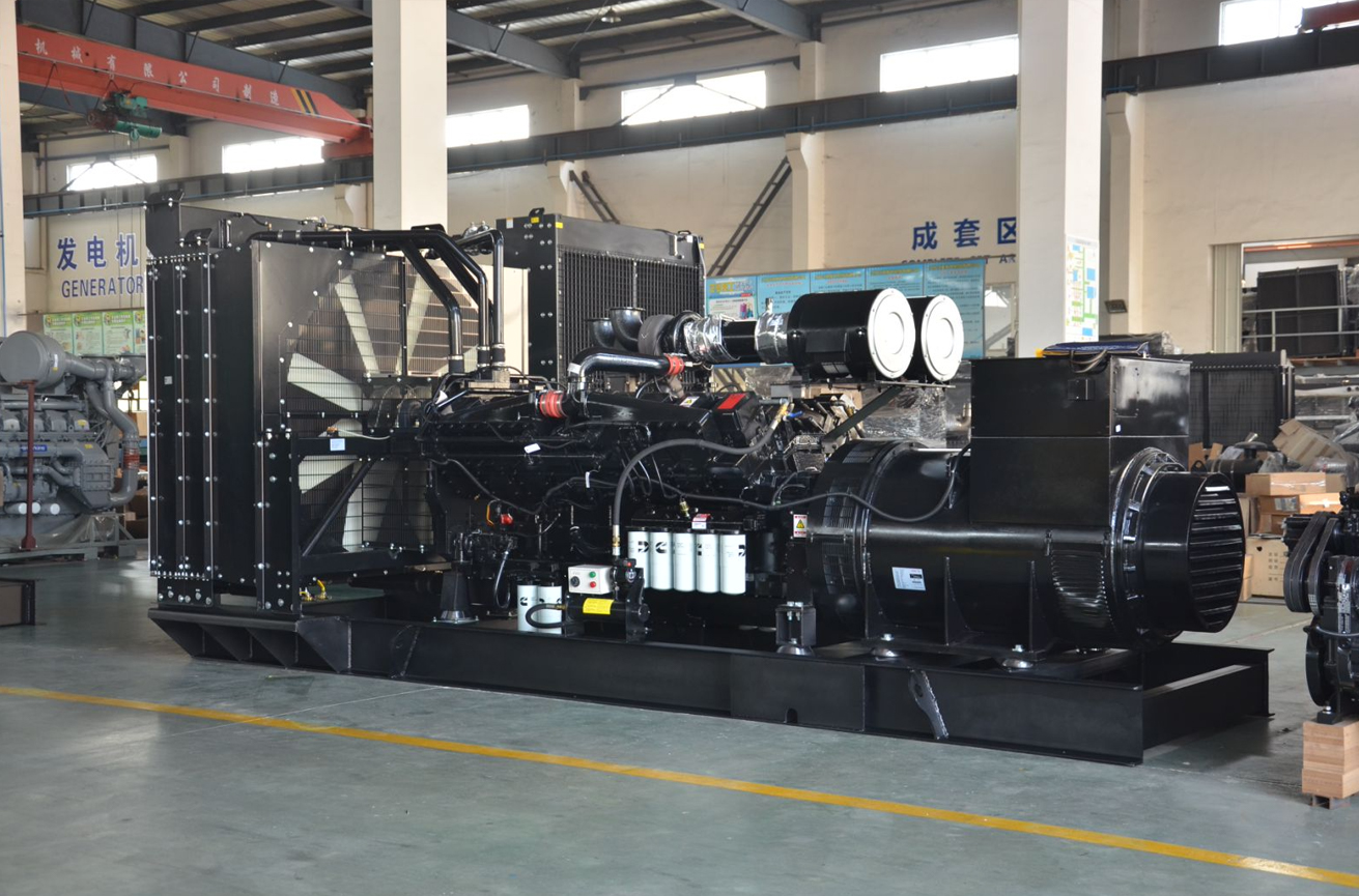
High Reliability
Equipped with Cummins’ advanced PT fuel system, offering unique overspeed protection and low-pressure fuel supply. Minimal piping reduces failure rates. Derived from superior overall design, delivering outstanding reliability.
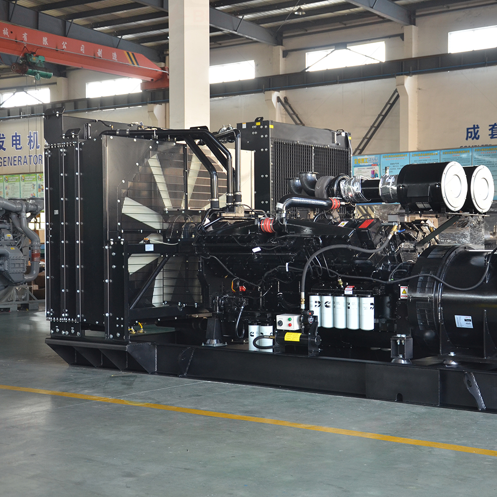
Superior Performance
- High-efficiency Cummins exhaust turbocharger ensures optimal air intake, enhancing engine efficiency.
- Pressure pulse exhaust manifold fully utilizes exhaust energy, further improving combustion and increasing low-load efficiency while reducing specific fuel consumption.
- High torque output, powerful performance, fast transient response, and exceptional torque reserve.
Easy Maintenance
Six-cylinder single-head integrated design with modularized structure ensures compactness. Components are detachable and highly reusable.